About a year ago, I joined Replay Golf Supply Inc. as a Golf Ball Technician. The work was simple but repetitive — sorting and counting golf balls by brand, sub-brand, and quality. It didn’t take long to notice how manual the entire process was. Counting thousands of golf balls by hand was slow, error-prone, and exhausting.
The first thought that came to mind was: why isn’t any of this automated?
That question started a personal project that took shape entirely outside of work — a golf ball counting machine I designed and built in my garage during spare hours.
The Origin
My first idea was ambitious: a fully automated system that could grade, split, and count golf balls in one go. After discussing it informally with my managers, we agreed that starting small made more sense — I would focus only on counting.
The goal was to create a machine that could quickly and reliably count golf balls into specific quantities, making one of the most repetitive tasks much faster.
In our workflow at Replay, we handle multiple standard counts:
- 48, 50, and 72 balls per bag
- 300, 334, and 350 balls per box
The large-count batches (300–350) are still done manually using the table and rails — operators simply load the correct number of balls by hand. The machine’s main purpose is to speed up smaller count batches, where most of the repetition happens.
The Concept
Golf balls are almost perfectly uniform — about 45 mm in diameter — which means they can be managed mechanically through controlled geometry rather than complex sensors. My approach was to use that consistency to measure by distance, letting the physical length of the rails define the count.
The design became a table-like structure with ten rails, each capable of holding 37 balls, giving a total capacity of 370 balls per batch.
The machine consists of two main parts:
- The hopper, which feeds balls into the start of the rails.
- The table, where the balls roll down toward the gates.
The rails start inside the hopper and run at roughly a 10° angle, allowing gravity to feed the balls toward the counting area in a controlled line.
How It Works
The machine operates using two gates:
- The count gate, positioned under the rails and movable along the table.
- The main gate, located at the end of the table to release balls into containers.
The process begins when the operator selects a desired count (e.g., 48, 50, or 72) using the button interface. The count gate automatically moves to a specific location corresponding to that count. Each position is hardcoded into the Arduino firmware, determined during calibration.
Before moving, the system always performs a reset: the gate travels back to a limit switch to define its zero position, then moves forward a set number of motor steps to reach the target count. The operator can verify the position using marks on the table, which provide a quick visual confirmation.
Once the gates are aligned, counting happens in three stages:
- The operator presses Open → the count gate closes to block any additional balls, and the main gate opens, releasing only the balls between the two gates.
- The counted balls roll down into the designated container.
- The operator presses Open again → the main gate closes and the count gate reopens, resetting the system for the next batch.
This cycle repeats rapidly, letting one operator manage consistent counts with minimal handling.
Materials and Construction
The structure is primarily wood, chosen for accessibility and rigidity. For components requiring complex geometry or frequent iteration, I used 3D-printed parts, and the rails were made from fiberglass rods in the first prototype.
In the next version, those rods will be replaced with polished wooden dowels — easier to mount securely.
Main build materials:
- Plywood and solid wood for the frame
- Polished wooden dowels for rails (next revision)
- 3D-printed brackets, gates, and mounts
- Stepper motors and motor drivers
- Arduino Uno for control
- Limit switches and buttons for input
Electronics and Control
The control system is fully self-contained on an Arduino Uno. No external computer is required.
Inputs:
- Buttons for count selection and gate control
- Limit switch for calibration
Outputs:
- Stepper motor drivers for gate movement
- Status LEDs for operation feedback
Each count setting corresponds to a hardcoded step distance, defined during calibration. The Arduino drives both stepper motors simultaneously to position the count gate accurately.
Design Challenges
The first working prototype proved the idea but revealed several design flaws that became clear during real use.
1. Rail fixation
The snap-fit rail mounts made it easy to remove the rails but didn’t hold them securely. Under load, some rails flexed or detached slightly, throwing off alignment.
2. Count gate movement
The automatic gate used two steppers on a plastic rail with plastic gears. Friction, weak materials, and poor rigidity caused high resistance and wear. Eventually, the automatic motion stopped working and the gate had to be positioned manually.
3. Gate design
The main gate sometimes bent under load, and the count gate occasionally allowed a few balls to slip through. Both designs lacked the strength and geometry to reliably block rolling balls.
4. Durability
Lightweight materials and 3D-printed parts were great for rapid prototyping but couldn’t handle continuous use. After several test runs, friction wear and small cracks began to appear.
Planned Improvements
The next version will prioritize reliability, durability, and simplicity over automation for its own sake.
Manual count gate:
The operator will manually move the gate to the desired position using table markings. Once set, that count can be repeated hundreds of times with no adjustments. This removes motors, friction issues, and alignment drift entirely.Redesigned rails:
Replace fiberglass rods with polished wooden dowels for a smoother rolling surface and better fastening. The rails will be bolted to the frame for rigidity and easy replacement.Vertical gates:
Both the main and count gates will move vertically, offering stronger blocking action.Reinforced structure:
Thicker wood, stronger joints, and better fasteners will make the system stable and more resistant to wear.Improved hopper geometry:
Adjusting the hopper shape to feed balls more evenly and reduce manual intervention.
Results and Testing
Even with its flaws, the prototype worked.
When counting 25,000 golf balls into 72-ball bags, the process takes roughly 2.5 hours. For comparison, a team of six people doing the same job manually would need 1.5–2 hours. The speed is close, but the machine eliminates most of the labor and keeps counts consistent without fatigue or distraction.
For large-count batches like 300, 334, or 350, the machine’s table and rails are still useful for staging and organizing balls, but the counts are done manually. The machine mainly targets the small, repetitive bag sizes where automation has the most benefit.
What’s Next
The “stable version” will be stronger, simpler, and easier to maintain. Once the mechanical platform is solid, I plan to reintroduce light automation — possibly optical sensing or load-based validation — to cross-check counts and reduce operator verification steps.
This project started as a curiosity from a repetitive job and turned into a real engineering exercise. It wasn’t a company project — just something I built alone in my garage, evenings and weekends — but it ended up being tested in production and worked.
The prototype proved the concept; the next version will prove the design.
Development Gallery
Below are photos, renders, and short clips from the development phase of the golf ball counting machine.
All visuals were taken at home during the design and testing stages, before the prototype entered production use.
| Photos |
|---|
 |
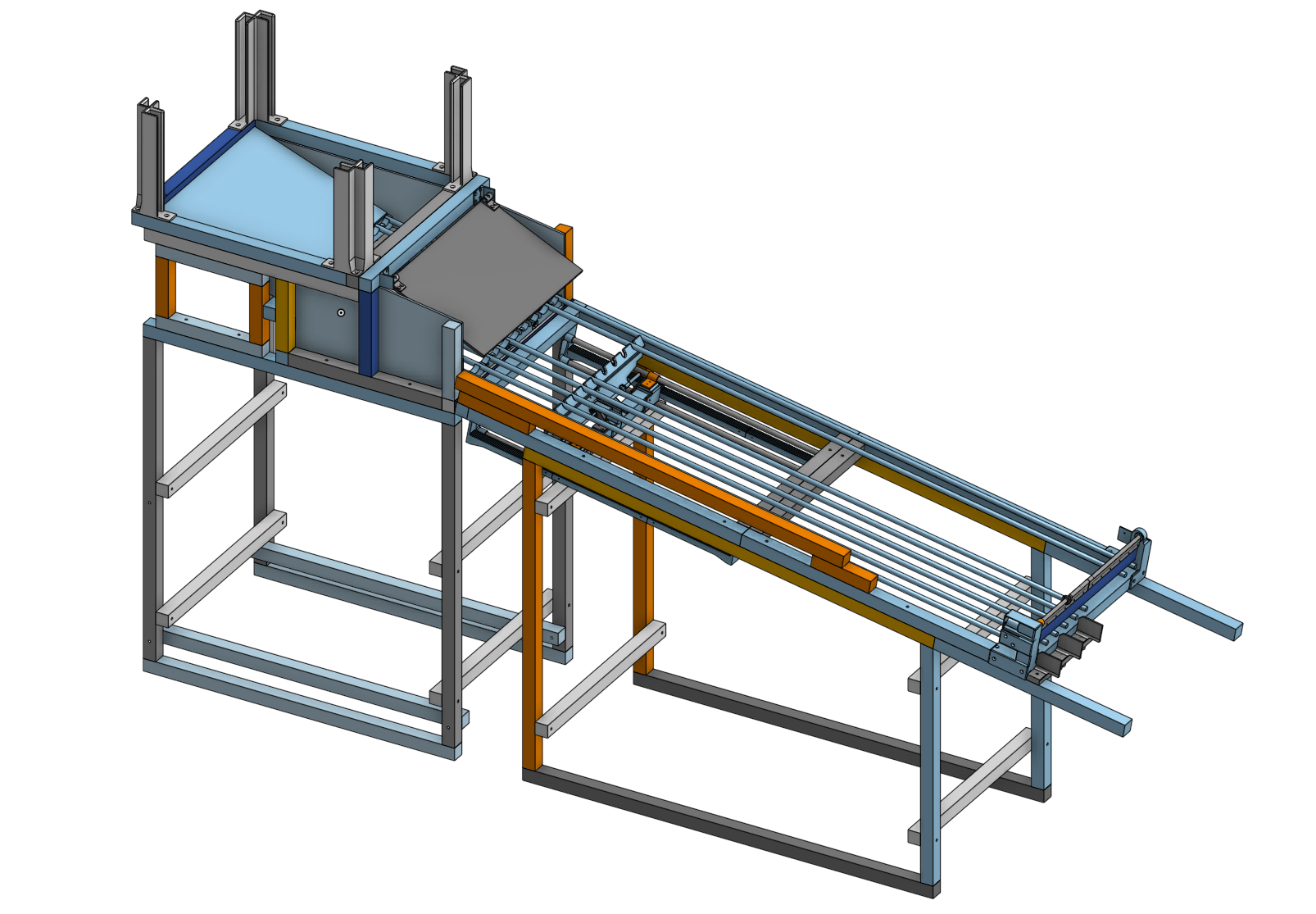 |
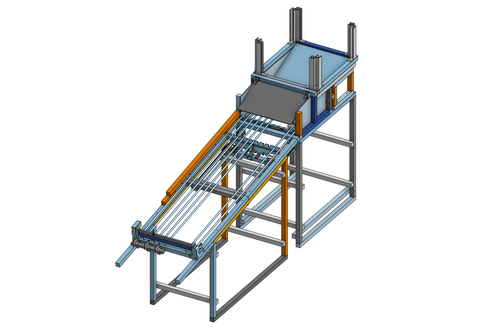
| CAD renders (incomplete; does not fully represent the final machine) |
 |
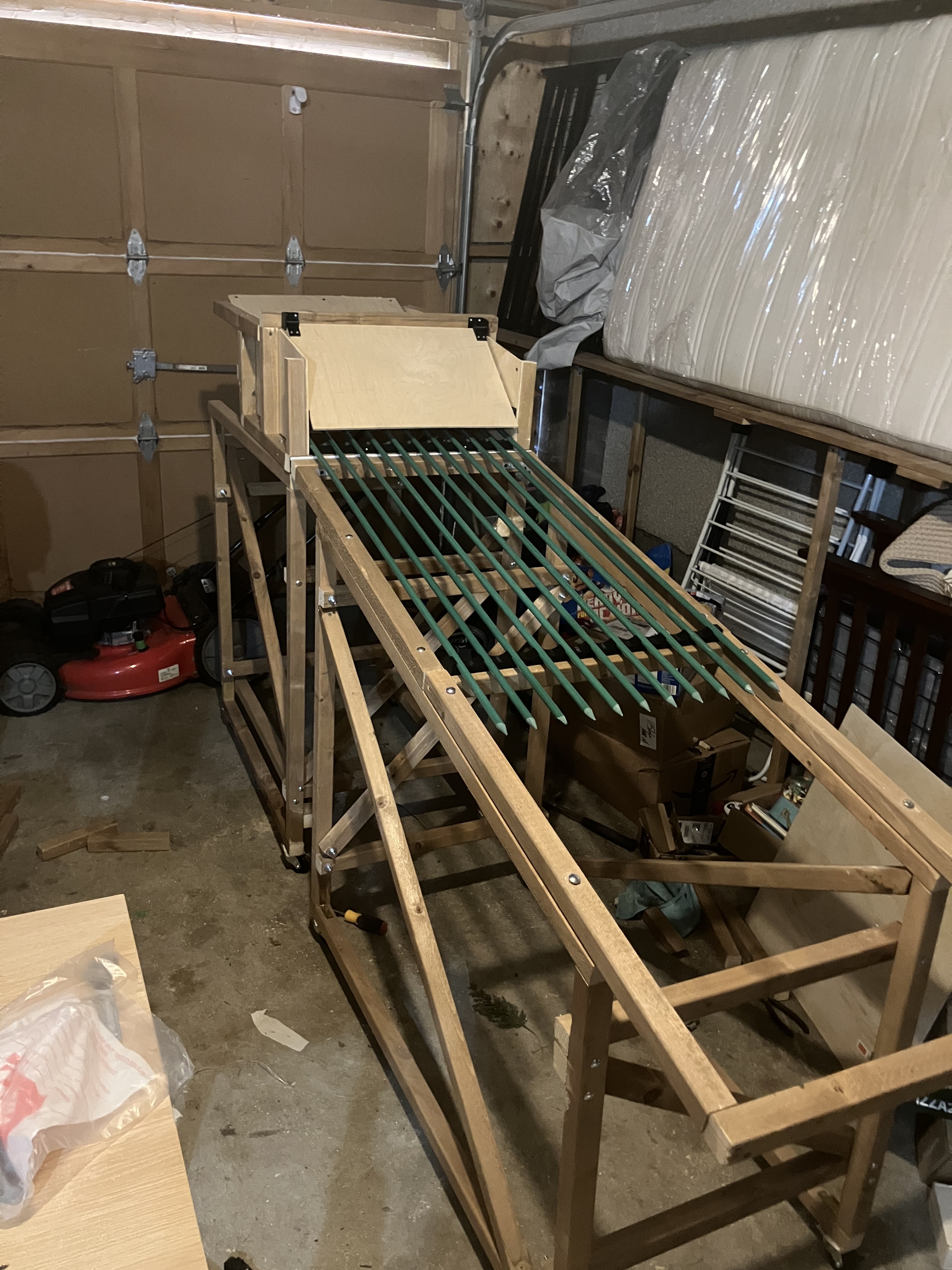 |
| Photo of the partially assembled machine with hopper and rails. |
Written and built independently by Pavlo Solodrai, 2025.
Developed entirely in my garage as a personal engineering project.